
Introduction
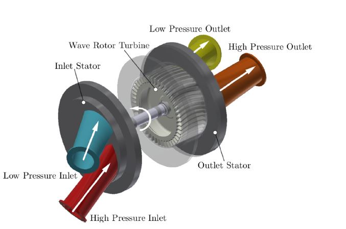
Over the past decades, numerous research studies have been dedicated toward the investigation of dynamic pressure exchange machinery, such as wave rotors. These devices use the energy carried in moving shock waves to transfer energy from one stream of fluid to another without the need to incorporate additional mechanical parts. This advantage, in combination with relatively large pressure ratio gains through shock wave compression and a high efficiency associated with this process, renders wave action devices an attractive technology for power generation. Opposed to crypto-steady flow devices, such as turbomachinery, wave rotors are inherently unsteady flow devices, where shock and expansion waves travel along discrete channels arranged around the circumference of a cylindrical drum. To each side of the spinning rotor, there are stator endplates containing port openings, as shown in Fig. 1. Exposing the rotor channels periodically to the ports then triggers shock and expansion waves. The application range for wave rotors outlined by the literature is diverse. The bulk of early studies focused on pressure exchangers with straight passage profiles for gas turbine topping cycles [1–8] and supercharging devices for internal combustion engines [9–16]. In recent years, the application to refrigeration cycles [17–19] and pressure-gain combustors [20–22] has come into the focus of consideration.
In comparison, little amount of attention has been given to wave turbines with cambered passage walls aimed at acting both as pressure exchangers while producing shaft power through momentum change of the flow [23–27]. Documentation of these endeavors is unfortunately fragmentary. The best documented and most successful example of a wave rotor engine was done by Pearson [23,24] at the University of Bath. Initial tests were conducted on a single cycle, through-flow wave rotor with helical passage shape leading to a power output of around 26kW at a rotational speed of 18,000 rpm. Further research was suspended after the engine was destroyed due to overspeeding. Further experiments by General Electric and General Power Corporation yielded insufficient shaft power generation and were not further pursued [25,26].